The liquid circulation energy recovery heat exchange system uses ethylene glycol solution as the heat transfer medium, and transfers the cold (heat) in the exhaust air to the ethylene glycol solution through a heat exchanger on the exhaust side, reducing (increasing) the temperature of the ethylene glycol solution. Then, the cooled (heated) ethylene glycol solution is transported to the heat exchanger on the fresh air side through a circulation pump, reducing (increasing) the temperature of the fresh air, reducing the load on the fresh air system, and reducing the operating cost of the entire air conditioning system.
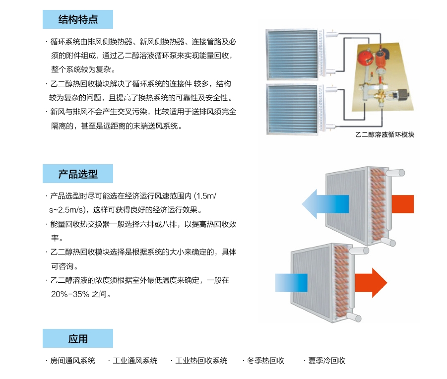
The liquid circulation energy recovery circulation system consists of an exhaust side heat exchanger, a fresh air side heat exchanger, connecting pipelines, and necessary accessories. Energy recovery is achieved through an ethylene glycol solution circulation pump, and the entire system is relatively complex. The ethylene glycol heat recovery module solves the problem of multiple connecting components and complex structure in the circulation system, and improves the reliability and safety of the heat exchange system. Fresh air and exhaust air will not produce cross pollution, making them more suitable for completely isolated supply and exhaust air, and even remote end supply air systems.

Liquid circulation energy recovery heat exchange system

