Архив категорий Информация об отрасли

Liquid circulation energy recovery heat exchange system

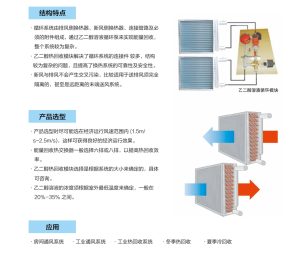
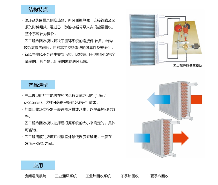
The liquid circulation energy recovery heat exchange system uses ethylene glycol solution as the heat transfer medium, and transfers the cold (heat) in the exhaust air to the ethylene glycol solution through a heat exchanger on the exhaust side, reducing (increasing) the temperature of the ethylene glycol solution. Then, the cooled (heated) ethylene glycol solution is transported to the heat exchanger on the fresh air side through a circulation pump, reducing (increasing) the temperature of the fresh air, reducing the load on the fresh air system, and reducing the operating cost of the entire air conditioning system.

The liquid circulation energy recovery circulation system consists of an exhaust side heat exchanger, a fresh air side heat exchanger, connecting pipelines, and necessary accessories. Energy recovery is achieved through an ethylene glycol solution circulation pump, and the entire system is relatively complex. The ethylene glycol heat recovery module solves the problem of multiple connecting components and complex structure in the circulation system, and improves the reliability and safety of the heat exchange system. Fresh air and exhaust air will not produce cross pollution, making them more suitable for completely isolated supply and exhaust air, and even remote end supply air systems.
Liquid circulation energy recovery heat exchange system
Liquid circulation energy recovery heat exchange system

How To Recovery Heat From Exhaust Gases Of The Drying

Recovering heat from exhaust gases of industrial drying processes is an effective way to improve energy efficiency, reduce costs, and lower emissions. Below is a concise guide on how to recover heat from dryer exhaust gases, focusing on practical steps, technologies, and considerations, tailored to your interest in air-to-air heat exchangers and waste heat recovery systems.

Steps to Recover Heat from Dryer Exhaust Gases

  1. Assess Exhaust Gas Characteristics:
    • Measure the temperature (typically >60°C for dryers), flow rate, and composition of the exhaust (e.g., moisture, dust, or corrosive elements).
    • Determine the sensible (temperature-based) and latent (moisture-based) heat content.
    • Example: Spray dryer exhaust in food processing may be 80–150°C with high humidity.
  2. Identify Heat Sink Opportunities:
    • Find nearby processes that can use recovered heat, such as preheating dryer inlet air, heating process water, or supplying facility HVAC.
    • Prioritize direct integration (e.g., preheating dryer air) for maximum efficiency.
  3. Select Appropriate Heat Recovery Technology:
    • Air-to-Air Heat Exchangers (Primary Focus):
      • Plate Heat Exchangers: Use metal or polymer plates to transfer heat from exhaust to incoming air. Polymer plates resist corrosion and fouling from moist, dusty exhaust.
      • Rotary Heat Exchangers: Rotating wheels transfer heat, ideal for high-volume flows.
      • Application: Preheat dryer inlet air, reducing fuel use by up to 20%.
    • Air 빨간색-Liquid Heat Exchangers:
      • Transfer heat to water or thermal oil for process heating or boiler feedwater.
      • Application: Heat cleaning water in food or chemical plants.
    • Heat Pumps:
      • Upgrade low-temperature exhaust heat for reuse in drying or other processes.
      • Application: Boost heat for dryer air preheating in dairy processing.
    • Direct Contact Heat Exchangers:
      • Exhaust gases contact water to recover heat and clean contaminants.
      • Application: Suitable for kilns or dryersWITH acidic exhaust.
    • Waste Heat Boilers:
      • Generate steam from high-temperature exhaust for process use or power.
      • Application: High-temperature dryers in ceramics.
  4. Design and Install the System:
    • Work with a supplier to design a system tailored to your dryer’s exhaust conditions and heat sink needs.
    • Ensure materials (e.g., polymer or stainless steel) resist fouling and corrosion.
    • Install the heat exchanger downstream of the dryer, with filters or scrubbers if dust is present.
    • Example: A polymer air-to-air exchanger can be retrofitted to a spray dryer to preheat inlet air, reducing energy costs.
  5. Monitor and Optimize Performance:
    • Use sensors to track temperature, flow, and efficiency of heat recovery.
    • Clean heat exchangers regularly to prevent fouling.
    • Adjust system settings to maximize heat transfer based on production demands.

Energy-Saving Performance of Gas-to-Gas Heat Recovery Technology in Drying Equipment

Gas-to-gas heat recovery technology significantly enhances the energy efficiency of drying equipment by recovering waste heat from hot exhaust gases and transferring it to the incoming cold air. This process reduces the energy demand for heating fresh air, thereby lowering fuel consumption and operating costs.

In drying systems, especially in industries like food processing, tobacco, paper, and sludge treatment, a large amount of thermal energy is typically lost through exhaust air. By integrating a gas-to-gas heat exchanger—commonly made from aluminum or stainless steel foil—this waste heat is captured and reused. The recovered energy can preheat the inlet air by 30–70%, depending on the system configuration and operating conditions.

Field applications have shown that the use of gas-to-gas heat recovery systems can reduce energy consumption by 15% to 35%, shorten drying cycles, and improve overall system efficiency. Additionally, it contributes to lower carbon emissions and better thermal control, making it a sustainable and cost-effective solution for modern drying processes.

international landscape of carbon trading markets

I. Overview of Major Carbon Trading Markets

1. European Union Emissions Trading System (EU ETS)

  • Launch: 2005, the world’s first and most mature carbon market.

  • Coverage: Power generation, manufacturing, aviation, and more.

  • Features: Cap-and-trade system with annually declining allowances; acts as a global price benchmark.

  • Development: Now in Phase IV (2021–2030), with tighter emission caps and expanded scope.

2. China National Carbon Market

  • Launch: Officially launched in 2021, initially covering the power sector.

  • Scope: The largest carbon market by volume of CO₂ emissions covered.

  • Mechanism: Based on allowances; draws experience from regional pilots (e.g., Beijing, Shanghai, Guangdong).

  • Future: Plans to expand to other high-emission industries such as steel and cement.

3. U.S. Regional Carbon Markets

  • No federal market, but two key regional systems exist:

    • California Cap-and-Trade Program: Linked with Quebec; highly active and comprehensive.

    • Regional Greenhouse Gas Initiative (RGGI): Covers electricity generation in northeastern U.S. states.

  • Features: Market-based, voluntary participation, robust design.

4. Other Countries and Regions

  • South Korea: Korea ETS (K-ETS) launched in 2015, steadily developing.

  • New Zealand: Operates a flexible ETS allowing international carbon credits.

  • Canada: Provinces like Quebec and Ontario run their own markets; Quebec is linked with California.


II. Types of Carbon Market Mechanisms

1. Compliance Markets

  • Government-mandated systems requiring companies to stay within emission caps or face penalties.

  • Examples: EU ETS, China’s national market, California’s system.

2. Voluntary Carbon Markets (VCM)

  • Non-mandatory participation; organizations or individuals purchase carbon credits to offset emissions.

  • Common project types: Forestry (carbon sinks), renewable energy, energy efficiency.

  • Certification bodies: Verra (VCS), Gold Standard, etc.


III. Global Trends and Integration

  1. Growing Interconnectivity Between Markets

    • Example: California and Quebec have linked carbon markets.

    • Under discussion: EU exploring potential linkage with Switzerland and others.

  2. Carbon Border Adjustment Mechanism (CBAM)

    • The EU’s proposed CBAM will tax high-carbon imports, pressuring other nations to adopt carbon pricing systems.

  3. Cross-Border Carbon Credit Flow

    • Under the Paris Agreement Article 6, a framework for international carbon credit exchange is forming, aiming to standardize and scale up global carbon trading.

  4. Integration with Nationally Determined Contributions (NDCs)

    • More countries are embedding carbon markets into their national climate strategies to meet NDC targets.


IV. Challenges and Opportunities

Challenges:

  • Diverse rules and standards hinder market linkage.

  • Voluntary markets vary in quality, and oversight is inconsistent.

  • Carbon price volatility can affect corporate planning.

Opportunities:

  • Net-zero goals drive rapid carbon market development.

  • Technological advancements (e.g., MRV systems, blockchain) enhance transparency.

  • Growing financial sector involvement; trend toward carbon market financialization.

Introduction to Industrial Ventilation Heat Recovery Systems

Industrial ventilation heat recovery systems are designed to improve energy efficiency in industrial facilities by recovering waste heat from exhaust air and transferring it to incoming fresh air. These systems reduce energy consumption, lower operating costs, and contribute to environmental sustainability by minimizing heat loss.

Key Components

  1. Heat Exchanger: The core component where heat transfer occurs. Common types include:
    • Plate Heat Exchangers: Use metal plates to transfer heat between air streams.
    • Rotary Heat Exchangers: Use a rotating wheel to transfer heat and, in some cases, moisture.
    • Heat Pipes: Utilize sealed tubes with a working fluid for efficient heat transfer.
    • Run-Around Coils: Use a fluid loop to transfer heat between air streams.
  2. Ventilation System: Includes fans, ducts, and filters to manage airflow.
  3. Control System: Monitors and regulates temperature, airflow, and system performance to optimize efficiency.
  4. Bypass Mechanisms: Allow the system to bypass heat recovery during conditions where it’s unnecessary (e.g., summer cooling).

Working Principle

  • Exhaust Air: Warm air from industrial processes (e.g., manufacturing, drying) is extracted.
  • Heat Transfer: The heat exchanger captures thermal energy from the exhaust air and transfers it to the cooler incoming fresh air without mixing the two air streams.
  • Supply Air: The preheated fresh air is distributed into the facility, reducing the need for additional heating.
  • Energy Savings: By recovering 50-80% of waste heat (depending on the system), the demand on heating systems like boilers or furnaces is significantly reduced.

Types of Systems

  1. Air-to-Air Heat Recovery: Directly transfers heat between exhaust and supply air streams.
  2. Air-to-Water Heat Recovery: Transfers heat to a liquid medium (e.g., water) for use in heating systems or processes.
  3. Combined Systems: Integrate heat recovery with other processes, such as humidity control or cooling.

Benefits

  • Energy Efficiency: Reduces energy consumption for heating, often by 20-50%.
  • Cost Savings: Lowers utility bills and operational costs.
  • Environmental Impact: Decreases greenhouse gas emissions by reducing reliance on fossil fuels.
  • Improved Indoor Air Quality: Ensures proper ventilation while maintaining thermal comfort.
  • Compliance: Helps meet energy efficiency and environmental regulations.

Applications

  • Manufacturing plants (e.g., chemical, food processing, textiles)
  • Warehouses and distribution centers
  • Дата-центры
  • Pharmaceutical and cleanroom facilities
  • Commercial buildings with high ventilation demands

Challenges

  • Initial Cost: High upfront investment for installation.
  • Maintenance: Regular cleaning of heat exchangers and filters is required to maintain efficiency.
  • System Design: Must be tailored to specific industrial processes and climates.
  • Space Requirements: Large systems may need significant installation space.

Trends and Innovations

  • Integration with IoT for real-time monitoring and optimization.
  • Advanced materials for heat exchangers to improve efficiency and durability.
  • Hybrid systems combining heat recovery with renewable energy sources (e.g., solar or geothermal).
  • Modular designs for easier installation and scalability.

Industrial ventilation heat recovery systems are a critical solution for energy-intensive industries, offering a balance of economic and environmental benefits while ensuring efficient and sustainable operations.

how does air to air heat exchanger work

An air-to-air heat exchanger transfers heat between two separate air streams without mixing them. It typically consists of a series of thin plates or tubes made of a thermally conductive material, like aluminum, arranged to maximize surface area. One airstream (e.g., warm exhaust air from a building) flows on one side, and another (e.g., cold incoming fresh air) flows on the opposite side.

Heat from the warmer airstream passes through the conductive material to the cooler airstream, warming it up. This process recovers energy that would otherwise be lost, improving efficiency in heating or cooling systems. Some designs, like cross-flow or counter-flow exchangers, optimize heat transfer by directing air in specific patterns. Effectiveness depends on factors like airflow rates, temperature difference, and exchanger design, typically recovering 50-80% of the heat.

Moisture transfer can occur in some models (e.g., enthalpy exchangers), which use special membranes to move water vapor alongside heat, useful for humidity control. The system requires fans to move air, and maintenance involves cleaning to prevent blockages or contamination.

industrial air to air heat exchanger | counterflow heat exchanger

An industrial air-to-air heat exchanger transfers heat between two air streams without mixing them, improving energy efficiency in HVAC systems, industrial processes, or ventilation. A counterflow heat exchanger is a specific type where the two air streams flow in opposite directions, maximizing heat transfer efficiency due to a consistent temperature gradient across the exchange surface.

Key Features of Industrial Air-to-Air Counterflow Heat Exchangers:

  • Efficiency: Counterflow designs achieve higher thermal efficiency (often 70-90%) compared to crossflow or parallel-flow exchangers because the temperature difference between the hot and cold streams remains relatively constant.
  • Construction: Typically made of materials like aluminum, stainless steel, or polymers for durability and corrosion resistance. Plate or tube configurations are common.
  • Applications: Used in industrial drying, waste heat recovery, data centers, and building ventilation to preheat or precool air.
  • Benefits: Reduces energy costs, lowers carbon footprint, and maintains air quality by preventing cross-contamination.
  • Challenges: Higher pressure drops due to the counterflow design may require more fan power. Maintenance is needed to prevent fouling or clogging.

Example:

In a factory, a counterflow heat exchanger might recover heat from hot exhaust air (e.g., 80°C) to preheat incoming fresh air (e.g., from 10°C to 60°C), saving significant heating energy.

industrial air to air heat exchanger | counterflow heat exchanger

industrial air to air heat exchanger | counterflow heat exchanger

Does a heat exchanger remove humidity?

A standard air-to-air heat exchanger primarily transfers heat between two airstreams and does not directly remove humidity. The airstreams remain separate, so moisture (humidity) in one airstream typically stays within that airstream. However, there are nuances depending on the type of heat exchanger:

  1. Sensible Heat Exchangers: These (e.g., most plate or heat pipe exchangers) only transfer heat, not moisture. Humidity levels in the incoming and outgoing air remain unchanged, though relative humidity may shift slightly due to temperature changes (warmer air can hold more moisture, so heating incoming air may lower its relative humidity).
  2. Enthalpy (Total Energy) Exchangers: Some advanced designs, like rotary wheel or certain membrane-based exchangers, can transfer both heat and moisture. These are called hygroscopic or enthalpy recovery ventilators (ERVs). The core material or wheel absorbs moisture from the humid airstream (e.g., warm, humid indoor air) and transfers it to the drier airstream (e.g., cold, dry outdoor air), effectively managing humidity levels to some extent.
  3. Condensation Effects: In certain conditions, if the heat exchanger cools humid air below its dew point, condensation may occur on the exchanger’s surfaces, removing some moisture from that airstream. This is incidental, not a primary function, and requires a drainage system.

So, a standard heat exchanger doesn’t remove humidity unless it’s an enthalpy-type ERV designed for moisture transfer or if condensation occurs. If humidity control is a goal, you’d need an ERV or a separate dehumidification system.

heat recovery wheel air handling unit

A heat recovery wheel in an air handling unit (AHU) is a device that improves energy efficiency by transferring heat and sometimes moisture between incoming fresh air and outgoing exhaust air. Here's a concise explanation:

How It Works

  • Structure: The heat recovery wheel, also called a rotary heat exchanger, thermal wheel, or enthalpy wheel, is a rotating cylindrical matrix typically made of aluminum or a polymer, often coated with a desiccant (e.g., silica gel) for moisture transfer. It has a honeycomb structure to maximize surface area.
  • Operation: Positioned between the supply and exhaust air streams in an AHU, the wheel rotates slowly (10-20 RPM). As it turns, it captures heat from the warmer air stream (e.g., exhaust air in winter) and transfers it to the cooler air stream (e.g., incoming fresh air). In summer, it can pre-cool incoming air.
  • Types:

    • Sensible Heat Wheel: Transfers only heat, affecting air temperature without changing moisture content.
    • Enthalpy Wheel: Transfers both heat (sensible) and moisture (latent), using a desiccant to adsorb and release water vapor based on humidity differences. This is more effective for total energy recovery.

  • Efficiency: Sensible heat recovery can achieve up to 85% efficiency, while enthalpy wheels may add 10-15% more by recovering latent heat.

Benefits

  • Energy Savings: Pre-conditions incoming air, reducing heating or cooling loads, especially in climates with large indoor-outdoor temperature differences.
  • Improved Air Quality: Supplies fresh air while recovering energy from exhaust air, maintaining indoor comfort.
  • Applications: Common in commercial buildings, hospitals, schools, and gyms where high ventilation rates are needed.

Key Considerations

  • Maintenance: Regular cleaning is critical to prevent dirt or clogs from reducing efficiency. Filters should be replaced, and the wheel inspected for buildup.
  • Leakage: Slight cross-contamination between air streams is possible (Exhaust Air Transit Ratio <1% in well-maintained systems). Overpressure on the supply side minimizes this risk.
  • Frost Prevention: In cold climates, wheel frosting can occur. Systems use variable speed control (via VFD), preheating, or stop/jogging to prevent this.
  • Bypass Dampers: Allow the wheel to be bypassed when heat recovery isn’t needed (e.g., during mild weather), saving fan energy and extending wheel life.

Example

In a hospital AHU, a heat recovery wheel might pre-heat incoming winter air (e.g., from 0°C to 15°C) using exhaust air (e.g., 24°C), reducing the heating system’s workload. In summer, it could pre-cool incoming air (e.g., from 35°C to 25°C) using cooler exhaust air.

Limitations

  • Space: Wheels are large, often the biggest AHU component, requiring careful installation planning.
  • Cross-Contamination: Not ideal for applications requiring complete air stream separation (e.g., labs), though modern designs minimize this.
  • Cost: Initial cost is high, but energy savings often justify it in high-ventilation settings.

What is the difference between the crossflow and counter flow heat exchangers?

The main difference between crossflow and counterflow heat exchangers lies in the direction in which the two fluids flow relative to each other.

  1. Counterflow Heat Exchanger:

    • In a counterflow heat exchanger, the two fluids flow in opposite directions. This arrangement maximizes the temperature gradient between the fluids, which improves heat transfer efficiency.
    • Benefit: The counterflow design is typically more efficient because the temperature difference between the fluids is maintained across the entire length of the heat exchanger. This makes it ideal for applications where maximizing heat transfer is crucial.

  2. Crossflow Heat Exchanger:

    • In a crossflow heat exchanger, the two fluids flow perpendicular (at an angle) to each other. One fluid typically flows in a single direction, while the other flows in a direction that crosses the first fluid’s path.
    • Benefit: While the crossflow arrangement is not as thermally efficient as counterflow, it can be useful when space or design constraints exist. It is often used in situations where the fluids must flow in fixed paths, such as in air-cooled heat exchangers or situations with phase changes (e.g., condensation or evaporation).

Key Differences:

  • Flow Direction: Counterflow = opposite directions; Crossflow = perpendicular directions.
  • Efficiency: Counterflow tends to have higher heat transfer efficiency due to the more consistent temperature gradient between fluids.
  • Applications: Crossflow is often used where counterflow isn't feasible due to design limitations or space constraints.

Need Help?
ru_RUРусский